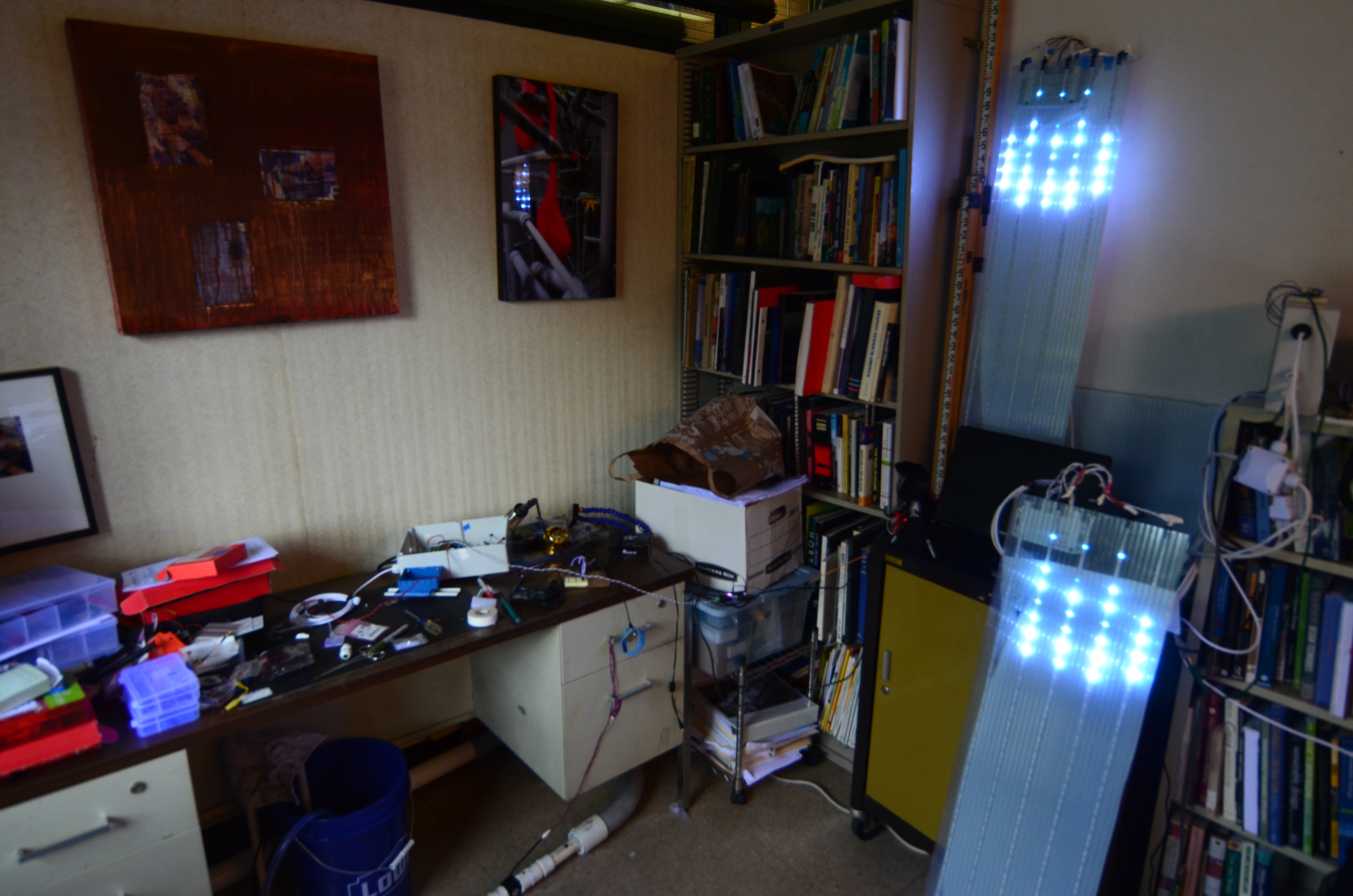
Over my fall 2017 sabbatical, I developed a prototype water meter display to research if displaying real-time water usage to a community could influence conservation as originally hypothesized in my 2014 DisplayScape project. Other sabbatical goals were developing my knowledge of electronic circuits and Arduino IDE (C+) programming, to teach courses that prototype environmental sensors, and also to create a work of data art.
InfraDRIP data stream on the web
When the InfraDRIP water meter node is running, the live data stream can be found at:
- https://io.adafruit.com/cppwaterrsch/dashboards/flow-monitor [stand by for a screen shot of io.adafruit.com]
Hardware v1.0
As of June 2018, the prototype InfraDRIP system is fully functional! The system has two hardware nodes: the water meter node, and the LED node controlling the animation sequence. The nodes communicate wifi to IO.Adafruit.com.
Most of the electronic components, hardware, and materials were purchased from: Adafruit.com, Sparkfun.com, Mouser.com, or Amazon.
Water Meter Node hardware:
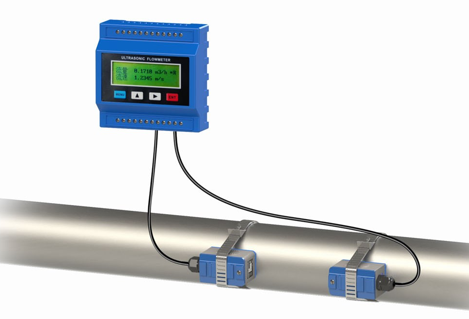
- TUF-2000M ultrasonic flow meter
- 24vdc 1A power supply
- CHIP Pro single board computer running linux (the only way we could connect to the TUF-2000m using MODBUS)
- 5vdc 1 amp USB port power supply
- Belden 3105A MODBUS/RS485 Cable
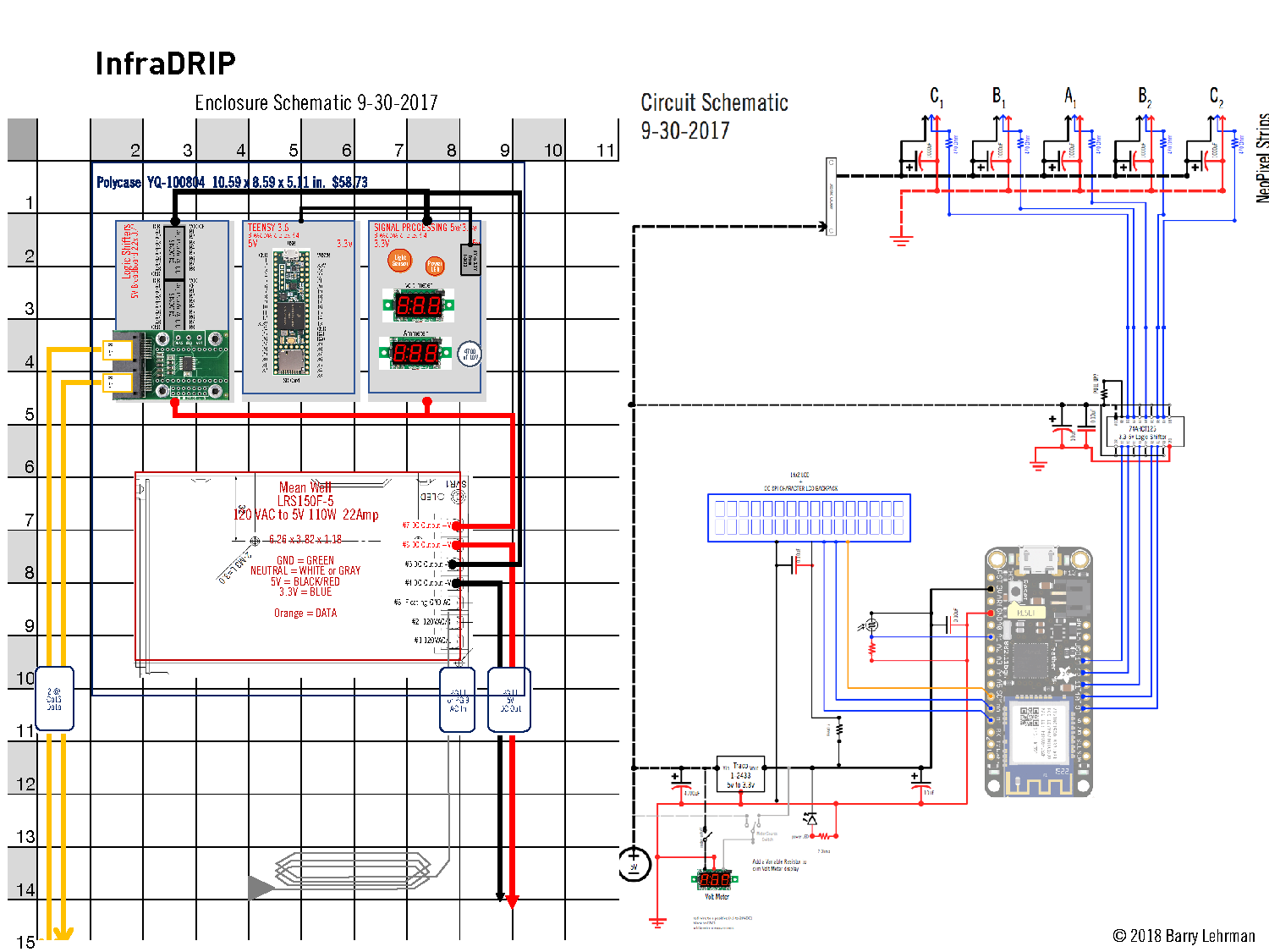
LED Display node:
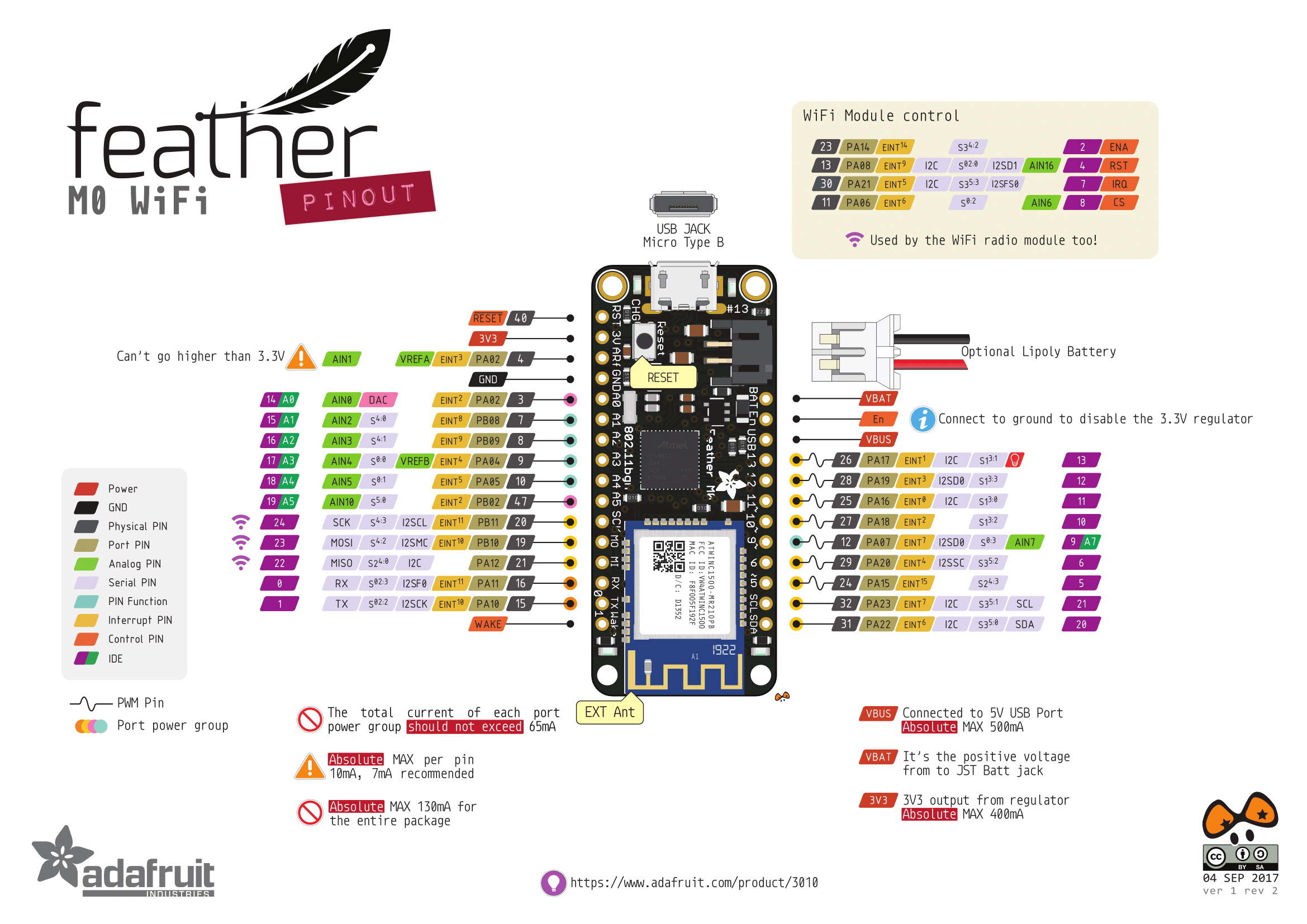
- Feather M0 atWINC1500 wifi development board (pinouts below)
- OLED 128×32 FeatherWing
- TSL2561 lux sensor
- 74AHCT125 logic shifter
- Mean Well 5V 22A 110w power supply
- 10 x 1 meter lengths of Neopixel 30 LED/m min strips in Twinwall polycarbonate panels
- Bunch of power conditioning capacitors: 10uF, 0.1uF, and 100uF
- 1000uF capacitors and 470ohm resisters for each neopixel strand
- A huge 4700uF cap smoothing everything (so it takes about 2 seconds for everything to turn on or off)
- Handful of circuit protection ESD varistors, PPTC resettable fuses, diodes, and pull down/pull up resistors
- Indicator LEDs
- 12awg speaker wire, 22awg hook-up wire, ribbon cable, and Cat5e cables
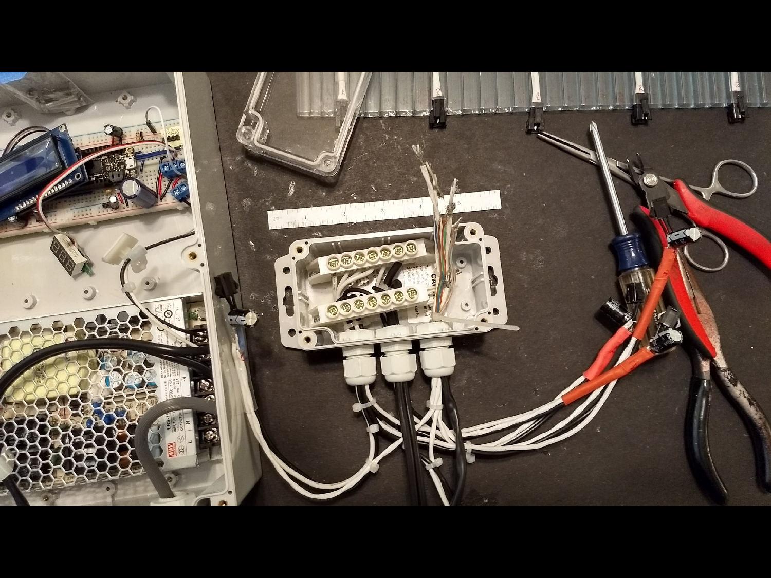
Both nodes are mounted in Polycase YQ-121006 NEMA enclosures with clear lids. PG9 and PG11 cable glands provide strain relief. Components are mounted with a variety of standoffs, clips, cable ties, and 3M Command Strip double-sided foam tape.
Hardware v0.5
Before selecting the winning components, I tested several other micro-controllers/development boards and other modules:
- Teensy 3.6 Cortex M4F 180MHz which I abandoned after finding the IDE interface to be awkward and less intuitive than Arduino’s IDE, and I broke the Teensy while soldering the headers.
- Feather M0+atWINC1500 got benched after I decided to instead use 915mhz radios to directly transmit the data between the nodes, and the wifi stack wasn’t as easy to use as the ESP32.
- Feather M0+RFM69 packet radio boards had antenna connection problems (don’t recommend soldering u.fl jacks as a beginner) and difficulty parsing the data strings to successfully send/receive them.
- ESP8266 ESP-12E NodeMcu LUA WiFi Development Board was a late-in-the-game substitution. These were 1/3rd the price of Adafruit Feather boards (though they lack the polished tutorials and support). The NodeMcu boards worked well and proved very simple to connect to the internet (though compiling the code took 3x as long as it did for the Cortex M0). Shelved the ESP8266s because I wasn’t able to fix a wiring fault on the perma-proto board that kept the middle strand of NeoPixels dark. So the atWINC1500 got dusted off.
Evaluated several level shifters connecting the microcontrollers running at 3.3v to NeoPixels that need 5v logic level. PJRC’s octoWS8211/74HCT245 (developed to connect Teensy boards to lots of NeoPixels) had minimally labeled pinouts that were awkwardly placed, so annoyingly needed a tangle of jumper wires to connect. 74HCT245 by itself
Then there were several RS485/MODBUS interface boards and raw chips (MAX485 variants) that didn’t work.
Process
My R&D process started by defining general functions of the InfraDRIP project (back as I developed the sabbatical proposal). Developing the concept for the physical configuration of the display and animation sequence, preceded researching hardware options (MCUs, LED varieties, enclosures, power supplies, et cetera), followed by evaluating component/module suitability based on performance, cost, and ease of use.
Once the main components were selected, I began laying out the circuits for both space and connectivity using block diagrams created in Excel. After components were acquired, circuits were first prototyped on solderless breadboards, with careful consultation of the spec sheets for the pin-outs of the various ICs and development boards. Detailed schematics of the circuits were created in Adobe Illustrator (as I can’t stand making ugly drawings) to refine the wire routing and placement of the supporting components (resisters, capacitors, voltage regulators, logic level shifters, terminal blocks, et cetera). Over a dozen iterations and variations of the circuits were developed.
Various sub-circuits were first tested in isolation to verify connections such as between the micro-controller and the LEDs, power supply to the LEDs/MCU, et cetera. Getting the Neopixels working was relatively simple (though a bit tricky to solder the seven way connections between data line + 470ohm resistor, +5v and ground to the 1000uf capacitor, and two ground lines back to the mcu and power supply). Getting the RFM radio modules and the SD card to work was more challenging (turned out that I needed to turn off the radios before I could write/read the SD card using the SPI bus).
Along the way, a soldering mishap destroyed the Teensy 3.5 I was evaluating, and I accidentally fried two panel meters and the 16×2 LCD display/I2C backpack with reversed polarity 😦In parallel to wiring up the circuits, I started writing the code (and teaching myself the basics of C++ along the way). This is where the excellent tutorials provided by Adafruit and Sparkfun really paid off as I was able to utilize the example code they provided for most of the basic functions.
Initial coding of the animation sequence began by manually transcribing hex color codes, sampled in photoshop into Excel. These frames were copied into the Arduino IDE and copy-edited as needed. Initial coding was for a 48-frame sequence that used less than 1/3rd of the M0’s program memory. To create a smoother sequence with just 8 milliseconds between frames, the final animation sequence is 128 frames long, filling 5,200 lines of code, once compiled it fills 70% of available memory. The speed of the animation sequence is controlled by a single universal variable, so it can be slowed down to one or two frames per second for editing and refining the visualization, while the OLED screen displays each frame number. Once editing was completed, all line numbers were commented out except multiples of 32.
Status/progress of the set-up code and loop code for the LED Node are displayed on the OLED display, and can be echoed on the serial monitor (though the serial feed was commented out in the final version). Displayed for the loop are: when it is connecting to IO.Adafruit, Flow data and delay between each drip, light levels and amount the Neopixels are being dimmed, then the frame numbers.
Once the circuits and basic functionality of the code were working as planned, duplicate circuits were soldered up on a full-size Perma-proto breadboard, then everything was mounted in the enclosures.
Water main mock-up
To calibrate the water meter and our uplink to the cloud, I fabricated a loop of 2″ pvc pipe with a small aquarium pump as a mock-up of a water main. Until the pilot study starts (see below), the animation is calibrated for the mock-up’s flow rate of 0 to 1 gallons per minute.
Research Assistant extraordinaire
In December, I encountered technical challenges with the MODBUS interface and working with the RFM 900mhz packet radios that were beyond my capacity to resolve. So I hired Joe Needleman, a white-hat hacker and brilliant talented computer science student as my research assistant in Winter Quarter 2018. Would not have been able to complete the project without him!
Field trial
Now that the prototype is working, I am coordinating a pilot study at one of the Cal Poly dorms. Stay tuned for details.
Funding
InfraDRIP v1.0 was a self-funded project with staff support by Cal Poly Facilities and University Housing.

You must be logged in to post a comment.